
Exclusive representation of Hasegawa
TRAMOZ GROUP is the exclusive European representative of the Japanese manufacturer HASEGAWA ELECTRIC CO., LTD. We supply non-contact voltage detectors, live-line approach alarms, voltage detectors from low voltage up to 550 kV and earthing sets – including advice, training and service.
What the service includes

TRAMOZ GROUP is the exclusive European representative of the Japanese manufacturer HASEGAWA ELECTRIC CO., LTD.
hasegawa-elec.co.jpHASEGAWA ELECTRIC CO., LTD. is a Japanese manufacturer of instruments for verifying the absence of voltage and for safe work on electrical equipment. Its product range covers non-contact voltage detectors and live-line approach alarms, voltage detectors from low voltage up to 550 kV, phase sequence indicators, short-circuiting and earthing sets, railway traction instruments and voltage detector testers.
As the exclusive representative for Europe we provide technical advice and help you select the right instrument, deliver it, train the operators and take care of service and periodic function checks. We also help you build the instruments into your work procedures and operating rules so they become a working part of your safety system rather than equipment left in a cabinet.
- Manufacturer
- HASEGAWA ELECTRIC CO., LTD.
- Manufacturer HQ
- Amagasaki, Hyōgo, Japan
- Representation
- TRAMOZ GROUP – exclusive for Europe
- Portfolio range
- Low voltage up to 550 kV, AC and DC
Hasegawa products
An overview of the range we supply. Each group includes product photos and technical data tables based on the manufacturer’s specifications.
Non-contact voltage detection and live-line approach warning
Instruments that signal the presence of voltage without touching the live part. They are used as additional protection when working near live parts, when entering substations and transformer stations, and when confirming that equipment is not energised. They do not replace the prescribed test for absence of voltage, but they significantly reduce the risk of human error.
| Model | Working voltage | Description |
|---|---|---|
| HXA-6 / HXA-6S | AC 3.3–33 kV | Personal approach alarm for overhead line workA wearable device that warns when approaching live parts of overhead lines. Its sensitivity is tuned specifically for line work, so it is not intended for work inside compact substations and kiosk stations. |
| HXA-30 / HXA-30S | AC 11–33 kV | Personal approach alarm for 33 kVThe same concept as the HXA-6 but with sensitivity for the 33 kV level. Suitable for maintenance of distribution lines. The S version comes with a silicone helmet band. |
| HXA-70 / HXA-70S | AC 66–110 kV | Personal approach alarm for 77 kVThe same concept as the HXA-6 but with sensitivity for the 77 kV level. Suitable for maintenance of transmission lines. The S version comes with a silicone helmet band. |
| HXW-6 | AC 6.6–33 kV | Wrist alarm for work inside compact substationsDesigned for work inside compact substations and kiosk stations. The device has no power switch and is permanently on standby, so it cannot be left switched off – one of the typical human errors is eliminated. |
| HXW-6W | AC 1–42 kV | Wrist alarm for compact substations – wide rangeThe same concept as the HXW-6, but with an extended range of AC 1 to 42 kV. Designed exclusively for work inside compact substations. No power switch, permanently on standby. |
| HXW-6WL | AC 400 V–22 kV | Wrist alarm with a range starting at low voltageThe L version is tuned for low voltage – from AC 400 V to 22 kV. Use it where a warning is needed at LV as well, not only at 6.6 kV. |
| HXG-1 | AC 3.3–77 kV | Telescopic live-state detectorA light telescopic instrument for additional confirmation of the de-energised state, typically after switching off and applying an earthing set. It is not a voltage detector and does not replace the prescribed test. |
| HXC-3K | AC 3.3–77 kV | Portable live-state detectorA pocket instrument for quickly finding out which parts of a substation or supply station are energised. Useful for inspections, work preparation and orientation in unfamiliar equipment. It is not a voltage detector. |
| HXR-20 / HXR-25 | AC 20 kV / AC 25 kV | Non-contact voltage detector for overhead contact linesSignals the voltage of the overhead contact line from a distance of roughly 2 m. Thanks to its directional characteristic you can tell which line is energised. The HXR-20 is for conventional lines (AC 20 kV), the HXR-25 for high-speed lines (AC 25 kV). |
| VOLTECT | AC 3.3–550 kV | Stationary voltage indication system for HV and EHVA permanently installed system that detects and displays without contact whether equipment is energised – in substations, on lines and in intake stations. It is installed without voltage transformers, which makes both installation and maintenance simple and economical. |
| ELL-1 | AC from 22 kV | Battery-free line voltage indicatorThe indicator lights up using energy drawn from the field of the line, so it needs no battery and no power supply. At night you can see at a glance which line is energised – useful when working in poor visibility. |
| HHV-6T | AC max. 7,000 V | Voltage indicator with a voice message and a flashing LED visible from all directions. |
| HH-6A | AC 3–7.2 kV | De-energised state indicator with audible and visual signalling; the hook shape holds even in strong wind. |
| WM series | AC 6.6–500 kV | Detector with visual indication by a rotating windmill powered by the energy of the tested object – it works without a battery. |
| Nominal voltage | HXA-6 | HXA-6S |
|---|---|---|
| 3.3 kV | 0.6 m | 0.8 m |
| 6.6 kV | 0.8 m | 1.1 m |
| 11 kV | 1.0 m | 1.4 m |
| 22 kV | 1.5 m | 2.0 m |
| 33 kV | 1.8 m | 2.5 m |
Distances are theoretical manufacturer values under standard conditions. Actual distance depends on the surroundings – confirm it on site before use.
| Nominal voltage | HXA-30 | HXA-30S |
|---|---|---|
| 11 kV | 0.7 m | 1.0 m |
| 22 kV | 0.9 m | 1.4 m |
| 33 kV | 1.2 m | 1.7 m |
| Nominal voltage | HXA-70 | HXA-70S |
|---|---|---|
| 66 kV | 1.5 m | 2.1 m |
| 77 kV | 1.6 m | 2.2 m |
| 110 kV | 1.9 m | 2.7 m |
| Nominal voltage | HXW-6 / HXW-6W |
|---|---|
| 6.6 kV | 0.6 m |
| 11 kV | 0.8 m |
| 22 kV | 1.1 m |
| 33 kV | 1.3 m |
Distances are theoretical manufacturer values under standard conditions. Actual distance depends on the surroundings – confirm it on site before use.
| Nominal voltage | HXW-6WL |
|---|---|
| 400 V | 0.25 m |
| 1 kV | 0.4 m |
| 6.6 kV | 1.0 m |
| 11 kV | 1.3 m |
| 22 kV | 1.9 m |
| Nominal voltage | Detectable distance | Approach limit |
|---|---|---|
| 3.3 kV | 5 cm | — |
| 6.6 kV | 10 cm | — |
| 11 kV | 33 cm | 15 cm |
| 22 kV | 90 cm | 25 cm |
| 33 kV | 120 cm | 35 cm |
| 77 kV | 230 cm | 76 cm |
Instrument photos
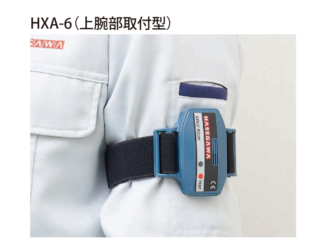
HXA-6 / HXA-6S 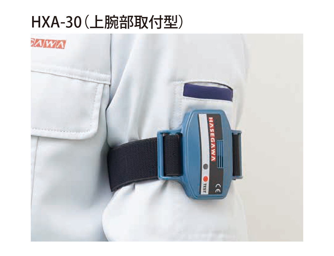
HXA-30 / HXA-30S 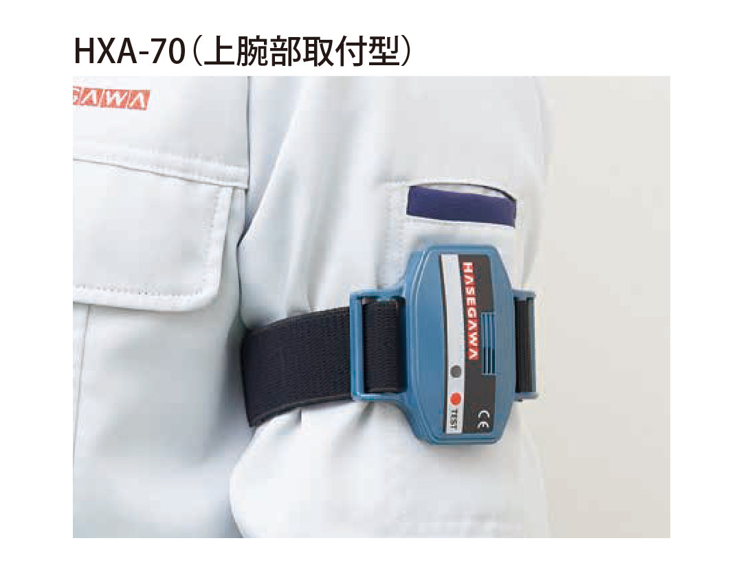
HXA-70 / HXA-70S 
HXW-6 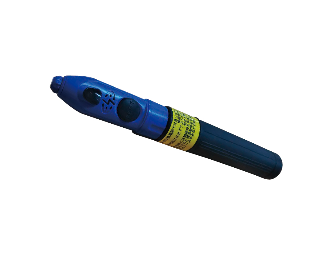
HXG-1 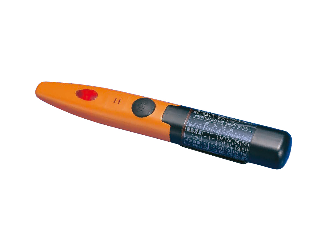
HXC-3K 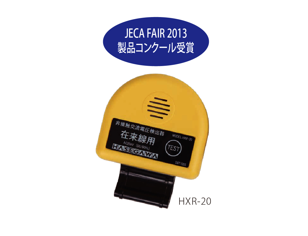
HXR-20 / HXR-25 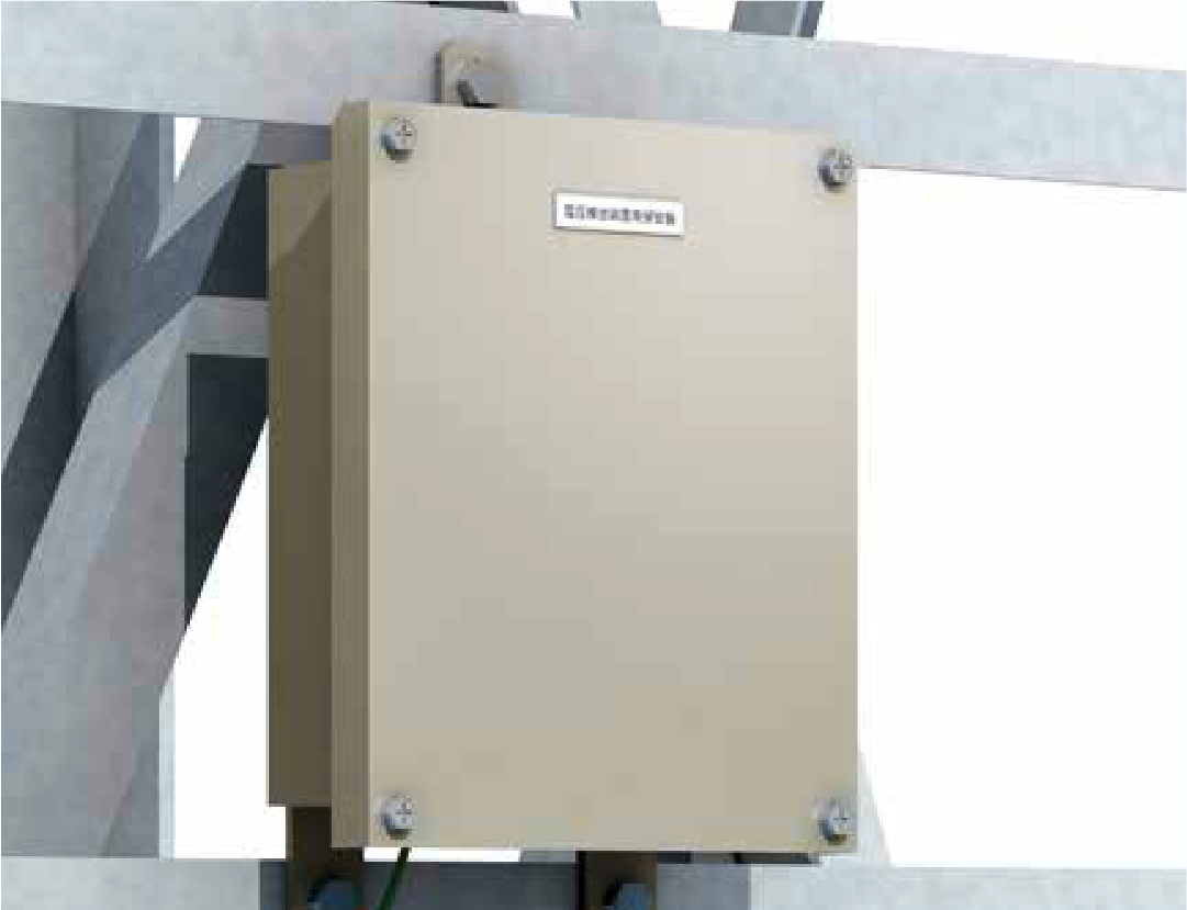
VOLTECT 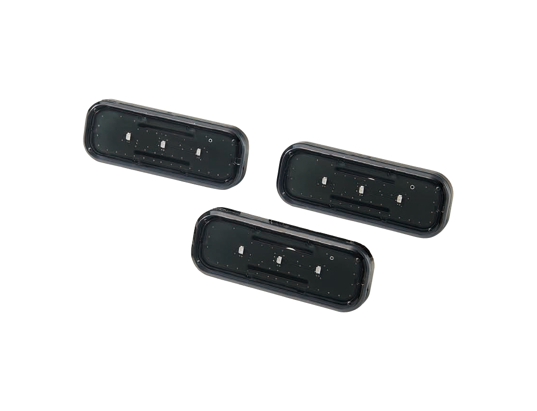
ELL-1 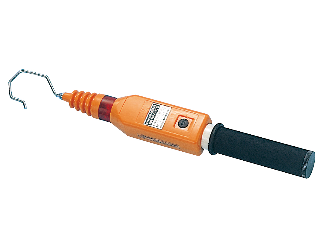
HHV-6T 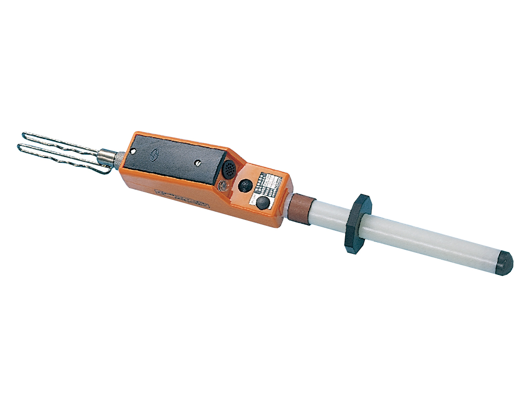
HH-6A 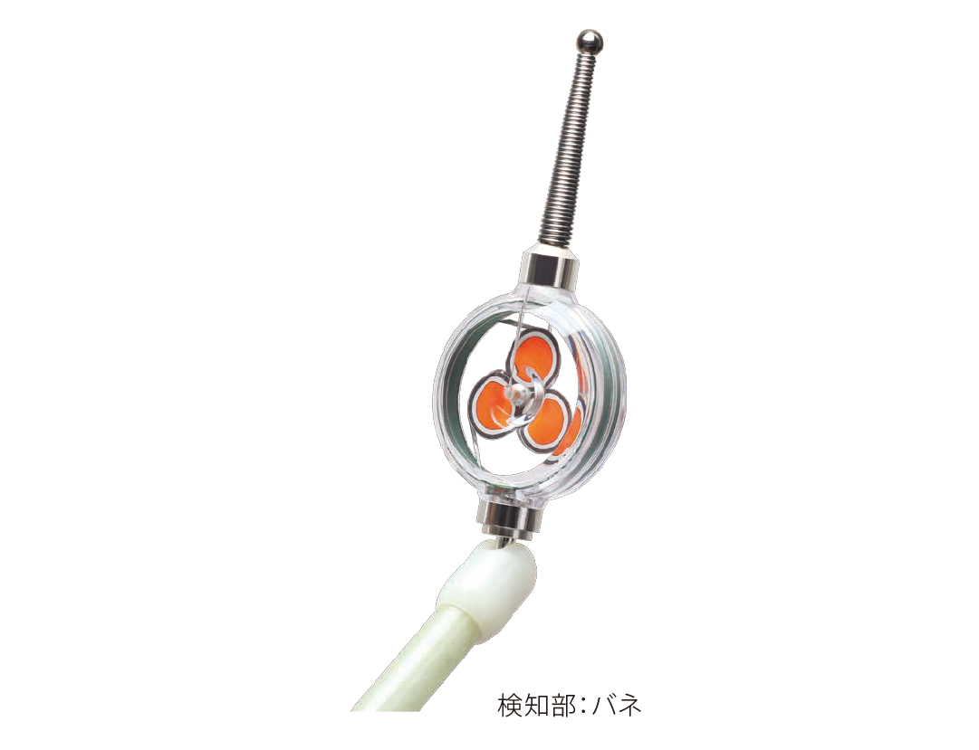
WM series
HV and EHV voltage detectors
Telescopic HST and HSR series detectors for verifying the absence of voltage on bare and insulated conductors. The insulating stick is made of FRP, the detector head is spring mounted against impact and the sensor is waterproof. Voltage is signalled by a high-luminosity flashing red LED and an intermittent buzzer, perceivable in bright daylight and in noisy environments. The dielectric strength of the insulating stick is AC 75 kV / 300 mm for 1 minute, power supply is 2× LR44 with about 4 hours of operation, working temperature −10 to +50 °C.
| Model | Working voltage | Description |
|---|---|---|
| HST-30 | AC 3–34.5 kV | Basic model for distribution networks, weight approximately 340 g. |
| HST-70 | AC 20–80.5 kV | Adjustable detector head angle for good visibility of the indication. |
| HST-170 | AC 60–195.5 kV | For the transmission grid, telescopes down to a much shorter length for transport. |
| HST-250 | AC 150–287.5 kV | The highest transmission grid levels, with an adjustable head. |
| HSR-500 | AC 250–550 kV | Detector for 500 kV lines with signalling readable in daylight and in noise. |
| HST-20N | AC/DC 3–25 kV | Lightweight model for both alternating and direct voltage. |
| HSR-90N | AC/DC 6–90 kV | Wide-range detector for AC and DC from HV to EHV. |
| HST-30L | AC 3–34.5 kV | Long version of the HST-30 for feeder lines, overall length approximately 9 m, weight 3 kg. Starting voltage 500 V ± 100 V. |
| HST-70L | AC 20–80.5 kV | Long version of the HST-70 for feeder lines, overall length approximately 9 m, weight 3 kg. Starting voltage 3,000 V ± 600 V. |
| HST-W80L | AC 20–80.5 kV | Long version for feeder lines, overall length approximately 9 m, weight 3 kg. Starting voltage 5,000 V ± 1,000 V – different sensitivity from the HST-70L. |
| HST-35V | AC 6–35 kV | Export version with audible and visual signalling for the 35 kV level. |
| HST-138V | AC 66–138 kV | Export version with audible and visual signalling for the 138 kV level. |
| HST-550V | AC 210–550 kV | Export version with audible and visual signalling for the 550 kV level. |
| HWB-35 | AC 6–35 kV | Non-contact detector with a universal joint for a shared insulating stick. |
| HWB-110 | AC 35–110 kV | Non-contact detector with a universal joint for the 110 kV level. |
| HWB-138 | AC 66–138 kV | Non-contact detector with a universal joint for the 138 kV level. |
| HWB-550 | AC 210–550 kV | Non-contact detector with a universal joint for the 550 kV level. |
| HWB-550A | AC 11–550 kV | Wide-range non-contact detector with a universal joint from 11 to 550 kV. |
| HWA-33X | AC 11–33 kV | IEC 61243-1 detector with interchangeable tips (hook / straight / Y) and three-step approach warning. |
| HWA-33P | AC 1–35 kV | Detector with four-step voltage indication according to the level of the measured object. |
| Parameter | HST-30 | HST-70 | HST-170 | HST-250 |
|---|---|---|---|---|
| Working voltage | AC 3–34.5 kV | AC 20–80.5 kV | AC 60–195.5 kV | AC 150–287.5 kV |
| Starting voltage (bare wire) | 500 V ± 20 % | 3 kV ± 20 % | 10 kV ± 20 % | 20 kV ± 20 % |
| Weight | 340 g | 530 g | 600 g | 1 030 g |
| Frequency | 50 / 60 Hz | 50 / 60 Hz | 50 / 60 Hz | 50 / 60 Hz |
| Battery | LR44 × 2 | LR44 × 2 | LR44 × 2 | LR44 × 2 |
| Battery life | 4 h | 4 h | 4 h | 4 h |
| Temperature | −10 to +50 °C | −10 to +50 °C | −10 to +50 °C | −10 to +50 °C |
| Stick dielectric strength | 75 kV AC / 300 mm, 1 min | 75 kV AC / 300 mm, 1 min | 75 kV AC / 300 mm, 1 min | 75 kV AC / 300 mm, 1 min |
| Parameter | HST-30L | HST-70L | HST-W80L |
|---|---|---|---|
| Working voltage | AC 3–34.5 kV | AC 20–80.5 kV | AC 20–80.5 kV |
| Starting voltage (bare wire) | 500 V ± 100 V | 3 000 V ± 600 V | 5 000 V ± 1 000 V |
| Dimensions | 9 m | 9 m | 9 m |
| Weight | 3 kg | 3 kg | 3 kg |
| Frequency | 50 / 60 Hz | 50 / 60 Hz | 50 / 60 Hz |
| Battery | LR44 × 2 | LR44 × 2 | LR44 × 2 |
| Model | Working voltage |
|---|---|
| HST-20N | AC/DC 3–25 kV |
| HSR-90N | AC/DC 6–90 kV |
| HSR-500 | AC 250–550 kV |
| HST-35V | AC 6–35 kV |
| HST-138V | AC 66–138 kV |
| HST-550V | AC 210–550 kV |
| Model | Working voltage | Key rating |
|---|---|---|
| HWB-35 | AC 6–35 kV | universal joint |
| HWB-110 | AC 35–110 kV | universal joint |
| HWB-138 | AC 66–138 kV | universal joint |
| HWB-550 | AC 210–550 kV | universal joint |
| HWB-550A | AC 11–550 kV | universal joint |
| HWA-33X | AC 11–33 kV | IEC 61243-1 |
| HWA-33P | AC 1–35 kV | 4-step indication |
Instrument photos
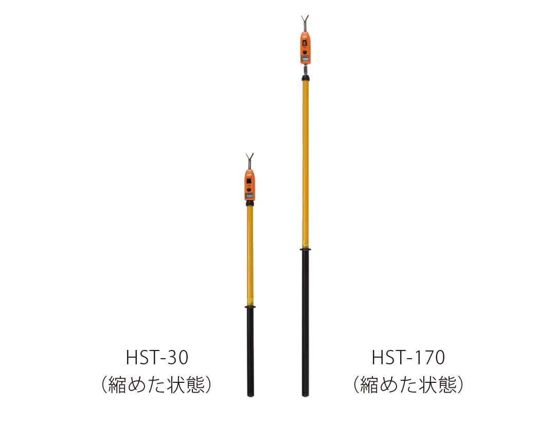
HST-30 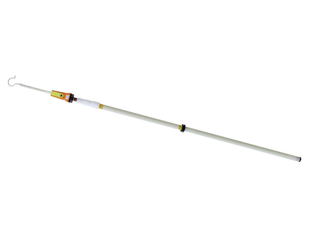
HSR-500 
HST-20N 
HSR-90N 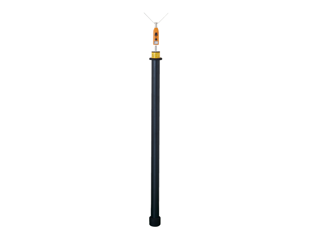
HST-30L HWB-35
Low voltage and combined HV/LV detectors
Hand-held detectors for everyday work on low voltage equipment and for levels up to 7 kV. Export models HSF-11, HSS-25B1 and HSS-36B1 cover European 11.4 / 25 / 36 kV networks. Models with a combined range distinguish low and high voltage by different signalling – intermittent for LV and continuous for HV.
| Model | Working voltage | Description |
|---|---|---|
| HTE-610-Y / M / I | AC 50–600 V | Standard model with a conductive rubber tip and adjustable sensitivity. |
| HTE-610L-R | AC 50–600 V | Version with an LED light and auto power-off that also serves as a battery status check. |
| HTE-610W | AC 50–1,000 V | Newer CAT III 1,000 V model, testing through insulation, adjustable sensitivity. |
| HTE-610WL | AC 50–1,000 V | W version with an LED light and auto power-off, CAT III 1,000 V. |
| HTE-700D / 700DL | AC 50–600 V, DC 12–750 V | Waterproof IPX4 design, powered by a single AAA cell, optionally with a light. |
| HT-670 | AC/DC 50–600 V | Sensitivity switching for bare and insulated conductors by a slide switch. |
| HSF-7 | AC 80–7,000 V | Standard model for the 6 kV level with LV/HV discrimination. |
| HSF-11 | AC 80–11.4 kV | Same concept as the HSF-7, but with a range for the European 11.4 kV level. |
| HSE-7T1 | AC 80–7,000 V | Pocket version for the 6 kV level with LV/HV discrimination. |
| HSS-6B1 | AC 80–7,000 V | Telescopic version for testing from a distance at 6 kV. LV is not detected with the stick extended. |
| HSS-25B1 | AC 80–25 kV | Telescopic version with the same form as the HSS-6B1, range up to 25 kV. |
| HSS-36B1 | AC 80–36 kV | Telescopic version with an expanded range up to 36 kV. |
| HSG-6 | AC 80–7,000 V | Lightweight 85 g version for testing from a distance at 6 kV. |
| HSN-6A2 | AC 80–7,000 V / DC 50–7,000 V | For dielectric strength testing up to AC 10.5 kV and DC 21 kV, with AC/DC discrimination and residual charge checking and discharging. |
| HST-1.5N | AC/DC 600–7,000 V | Sturdy and light FRP insulating stick, supplied with a 7 m earthing lead. |
| HSE-7G | AC 60–7,000 V | Version for telecommunication pole work with a range starting at 60 V. |
| Model | AC | DC | Battery | Weight |
|---|---|---|---|---|
| HTE-610-Y / M / I | 50–600 V | — | LR44 × 2 | 22 g |
| HTE-610L-R | 50–600 V | — | LR44 × 2 | — |
| HTE-610W | 50–1 000 V | — | LR44 × 2 | 22 g |
| HTE-610WL | 50–1 000 V | — | LR44 × 2 | 22 g |
| HTE-700D / 700DL | 50–600 V | 12–750 V | AAA × 1, IPX4 | — |
| HT-670 | 50–600 V | 50–600 V | — | — |
| HSF-7 | 80–7 000 V | — | — | — |
| HSF-11 | 80–11.4 kV | — | — | — |
| HSE-7T1 | 80–7 000 V | — | — | — |
| HSS-6B1 | 80–7 000 V | — | — | — |
| HSS-25B1 | 80–25 kV | — | — | — |
| HSS-36B1 | 80–36 kV | — | — | — |
| HSG-6 | 80–7 000 V | — | — | 85 g |
| HSN-6A2 | 80–7 000 V | 50–7 000 V | — | — |
| HST-1.5N | 600–7 000 V | 600–7 000 V | — | — |
| HSE-7G | 60–7 000 V | — | — | — |
Instrument photos
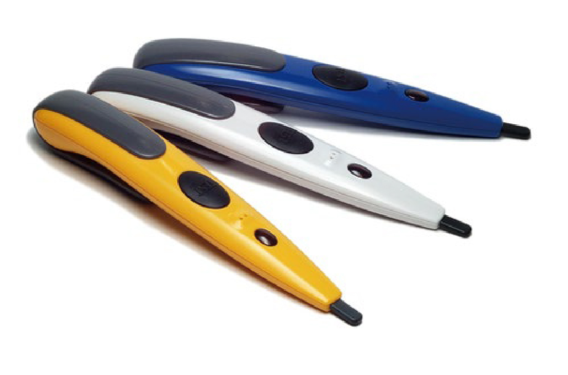
HTE-610-Y / M / I 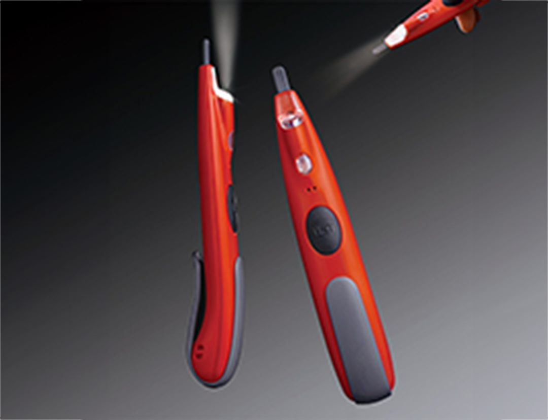
HTE-610L-R 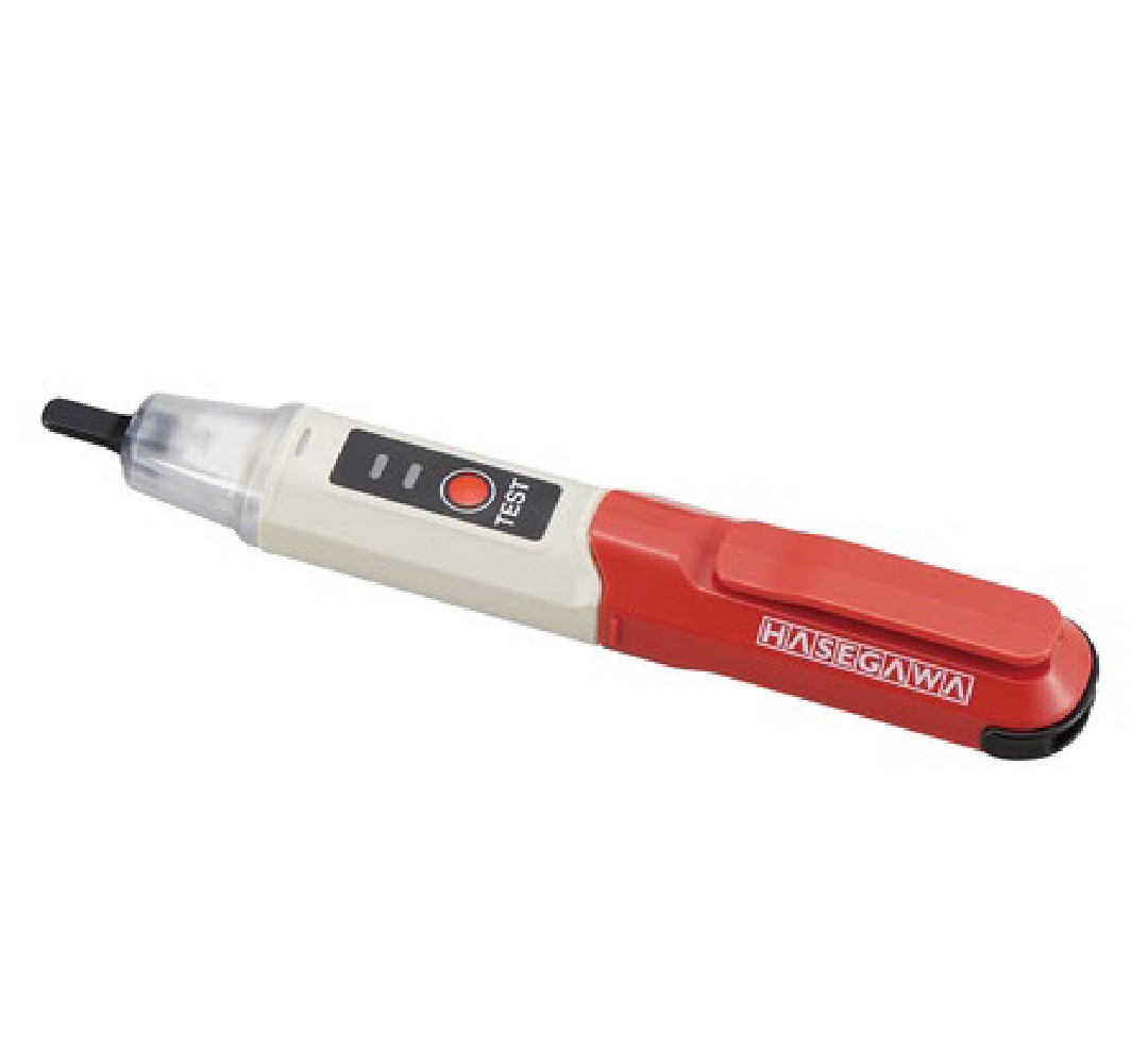
HTE-700D / 700DL 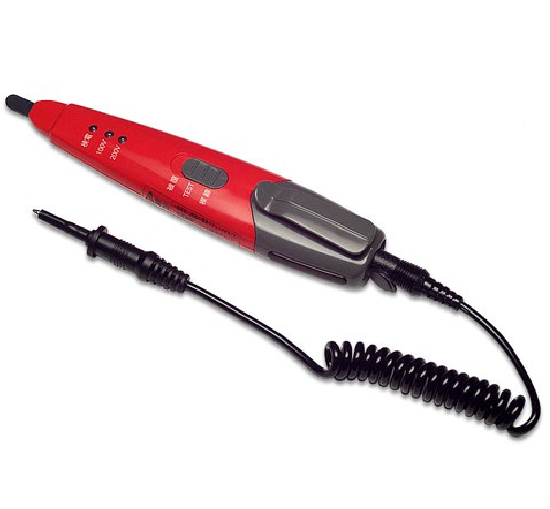
HT-670 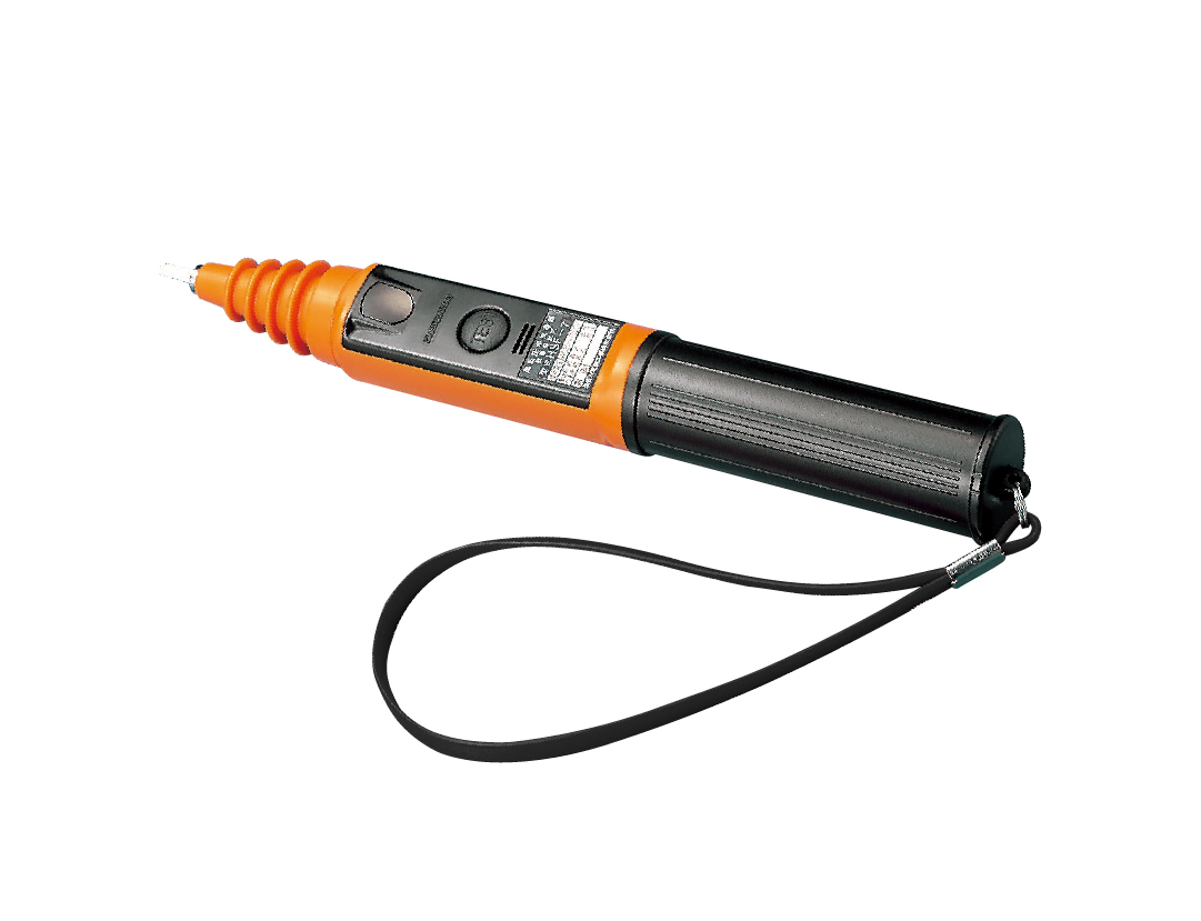
HSF-7 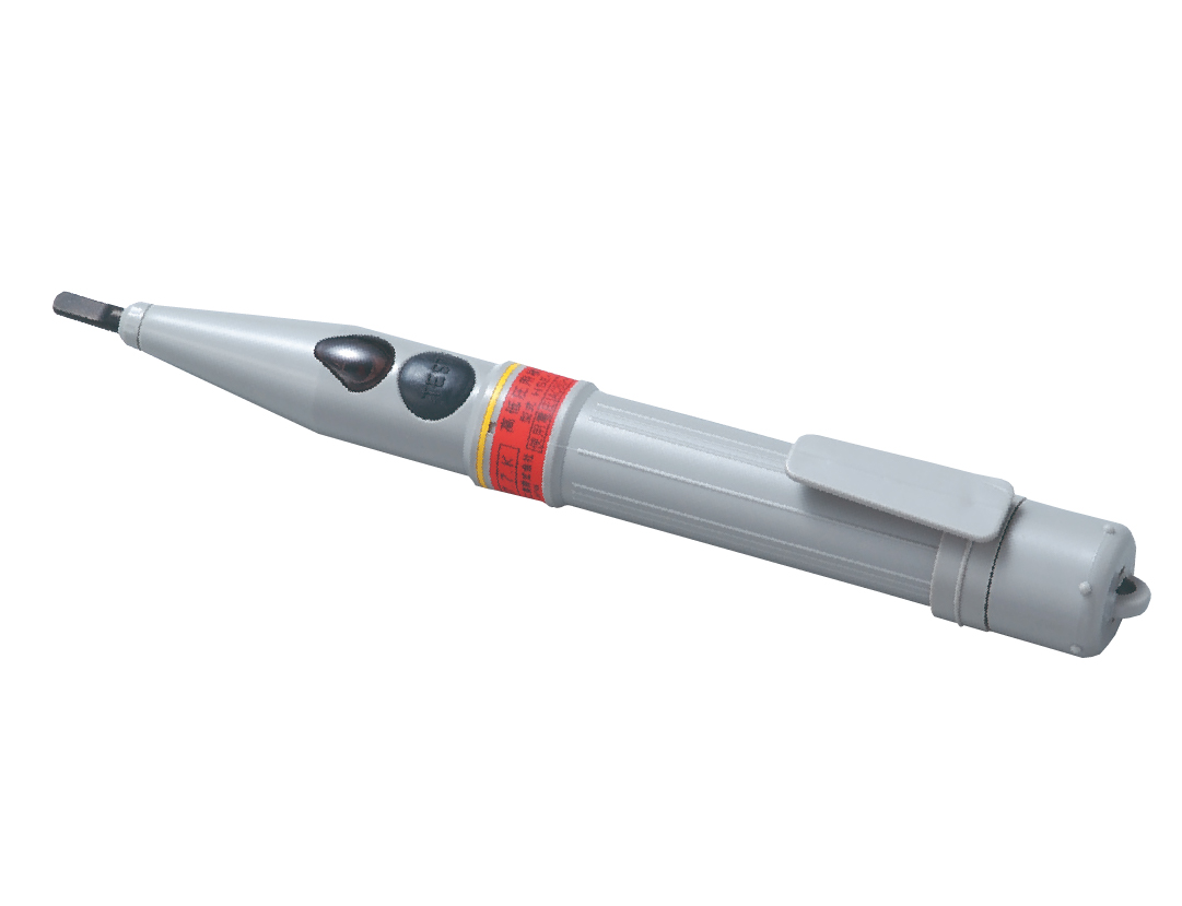
HSE-7T1 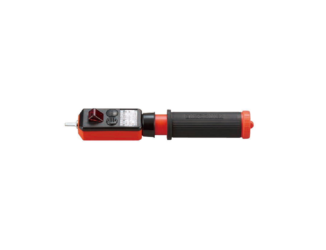
HSS-6B1 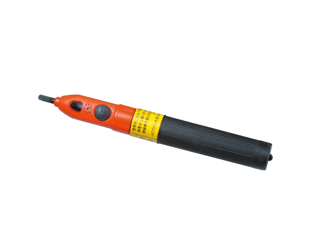
HSG-6 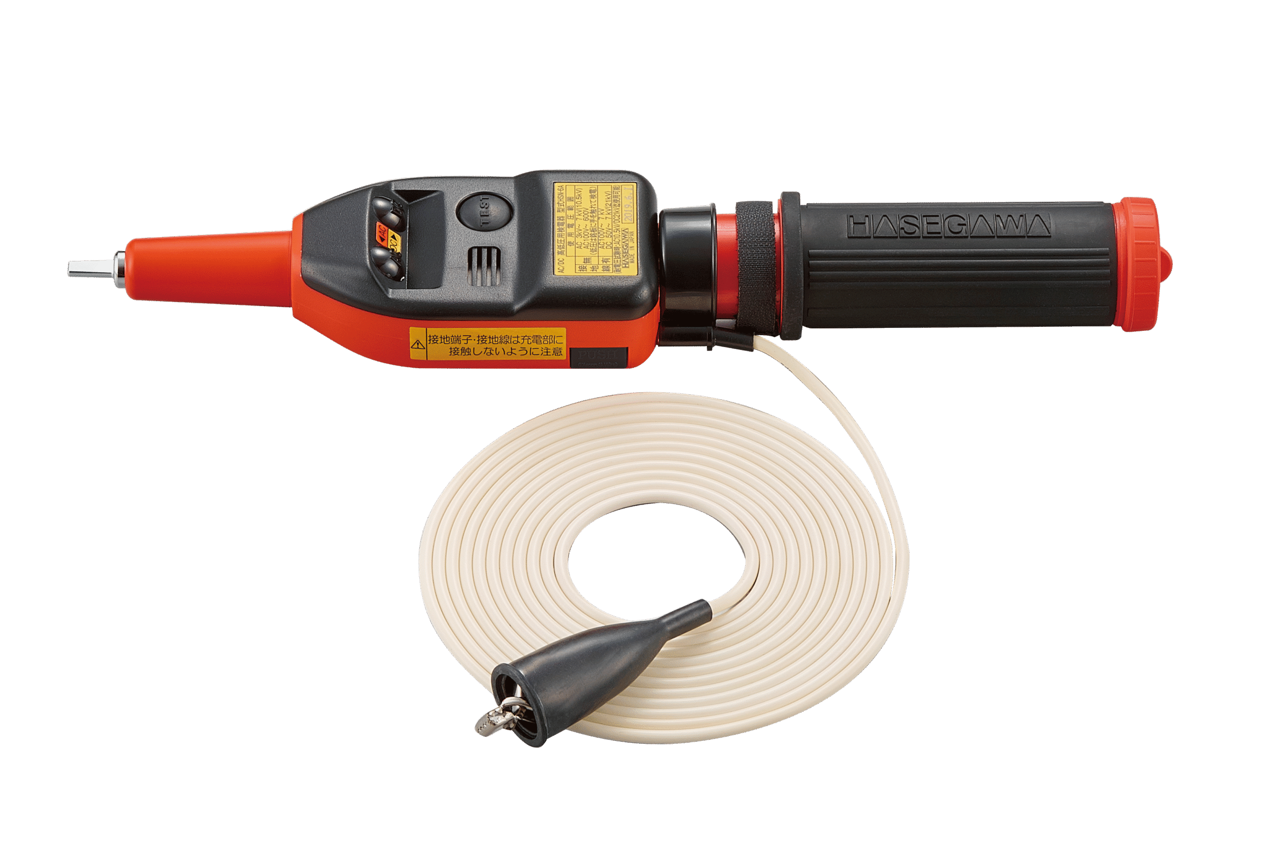
HSN-6A2 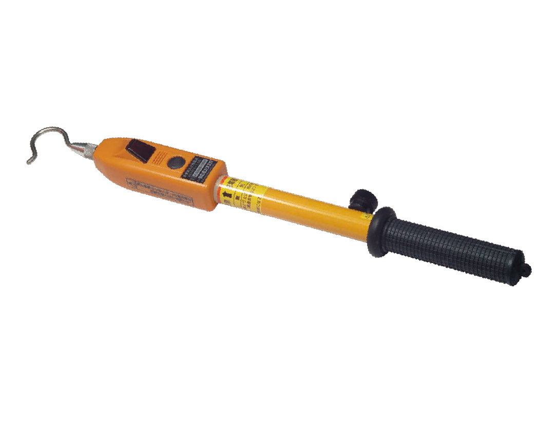
HST-1.5N 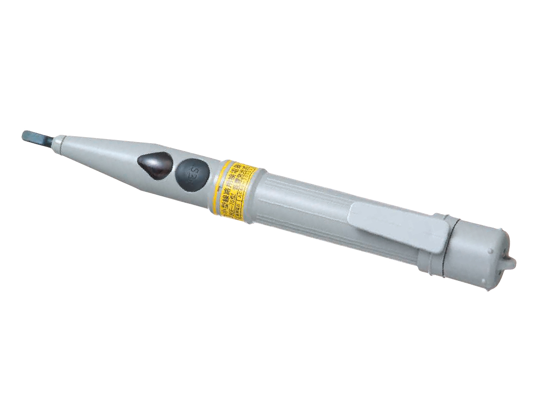
HSE-7G
Phase sequence and phase coincidence indicators
Instruments for checking phase coincidence and phase sequence when connecting and switching equipment. They measure through the conductor insulation or at test terminals, so there is no need to touch bare parts.
| Model | Working voltage | Description |
|---|---|---|
| HPI-A6 | AC 3–7 kV | Sensors separated by an optical fibre. Used alone they work as a voltage detector, used in pairs they check phase coincidence and sequence. |
| HPI-A6F | AC 3.3–6.6 kV / 22 / 33 kV | Optical fibre, measuring through insulation or at 6.6 / 22 / 33 kV test terminals. |
| HPI-S6 | AC 6.6 kV | Optical fibre, specified for the 6.6 kV level. |
| HPI-S20 | AC 22–34.5 kV | Optical fibre, specified for 22 to 34.5 kV. |
| HPR series | AC 3.3–34.5 kV | Wireless link between the sensors, checking phase coincidence and phase sequence without a connecting cable. |
| HPL-200 | AC 80–600 V, 3 phase | Non-contact checking of phase sequence and phase coincidence through the conductor insulation, for cross sections of 2–100 mm², with a magnet for hands-free work. |
| HPL-200W | AC 70 V–1 kV, 3 phase | Wider range than the HPL-200 – from 70 V to 1 kV. Same concept, measurement through insulation, magnetic mounting. |
| Model | Working voltage |
|---|---|
| HPI-A6 | AC 3–7 kV |
| HPI-A6F | AC 3.3–6.6 kV / 22 / 33 kV |
| HPI-S6 | AC 6.6 kV |
| HPI-S20 | AC 22–34.5 kV |
| HPR | AC 3.3–34.5 kV |
| HPL-200 | AC 80–600 V, 3f / 2–100 mm² |
| HPL-200W | AC 70 V–1 kV, 3f / 2–100 mm² |
Instrument photos
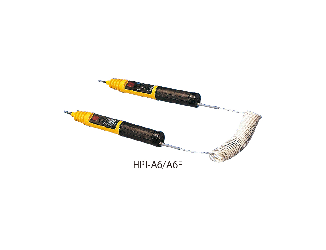
HPI-A6 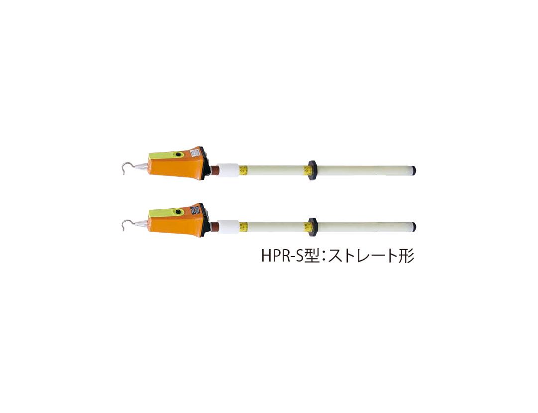
HPR series 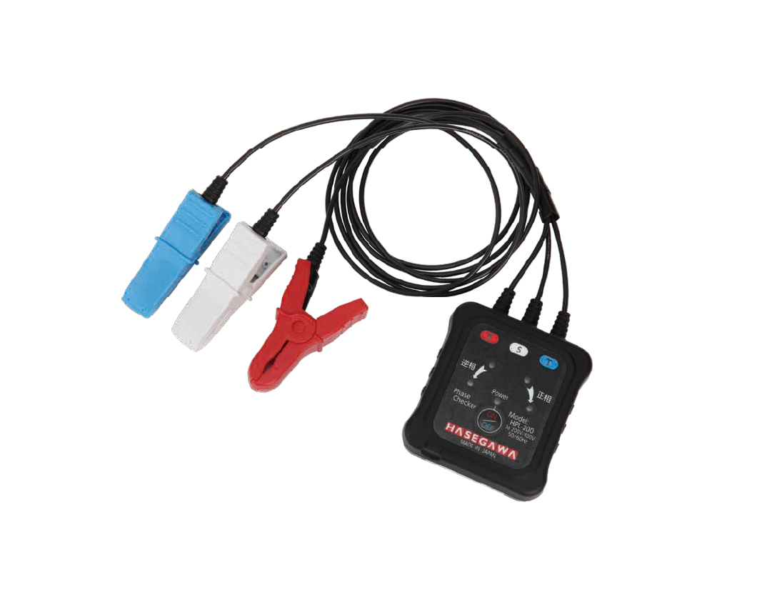
HPL-200
Short-circuiting and earthing sets and railway traction
Sets and instruments for traction power supply, where high short-circuit currents and residual voltage have to be handled. Earthing sets are supplied as custom assemblies – according to the tip fitting, rod length, earth lead cross section and length and the type of earthing clamp.
| Model | Working voltage | Description |
|---|---|---|
| Earthing hooks (standard / type R) | DC 1,500 V | Short-circuiting and earthing sets for DC traction rated at 4,000 A / 0.2 s. Assembled from SA106-A, SA106-C and SA106-S tip fittings, rods from 0.5 to 6 m, leads of 38, 60 and 100 mm² and SA120 clamps. In the type R the rod and the conductor form one unit, so the lead does not sag, and it is 20% lighter than the earlier design. |
| HVC-1.5N3 / HVC-1.5N3S / HVC-1.5N3M | DC 1,500 V | Detectors for overhead contact lines, supply stations and monorails, displaying the decrease of residual voltage and prompting the pre-use check. |
| HVC-750N3 | DC 750 V | Version for the third rail with voltage measurement, fast discharge of residual charge and a dedicated tip fitting for a firm grip. |
| HST-W80JS | AC 20–80.5 kV | Detector for AC overhead contact lines of conventional and high-speed railways, with a standby indication. |
| HST-22JX | AC 20 kV | Induced voltage detector for a switched-off contact line on conventional railways. Used after the absence of voltage has been verified and earthing applied; it is not a voltage detector. |
| HST-25JX | AC 25 kV | Same function as the HST-22JX, but for high-speed lines at AC 25 kV. |
| HSR-1.5NJ | AC 6.6 kV / DC 600–7,000 V | Detector for DC traction and AC 7 kV with a clip earth. DC range starting at 600 V. |
| HSR-1.5NJ1 | AC 6.6 kV / DC 1,000–7,000 V | Same concept as the HSR-1.5NJ, but with a DC range starting at 1,000 V. |
| HSR-1.5NR | AC 6.6 kV / DC 1,000–7,000 V | Magnet earth and residual-charge discharge indication. |
| EFS-1 Circuit Guard | DC 1,500 V | Prevents a track circuit short caused by incorrect earthing, keeps work safe when several earths are applied and reduces induced voltage with a capacitor. |
| Model | Working voltage | Key rating |
|---|---|---|
| SA106 / type R | DC 1 500 V | 4 000 A / 0.2 s |
| HVC-1.5N3 / N3S / N3M | DC 1 500 V | — |
| HVC-750N3 | DC 750 V | — |
| HST-W80JS | AC 20–80.5 kV | — |
| HST-22JX | AC 20 kV | — |
| HST-25JX | AC 25 kV | — |
| HSR-1.5NJ | AC 6.6 kV / DC 600–7 000 V | clip |
| HSR-1.5NJ1 | AC 6.6 kV / DC 1 000–7 000 V | clip |
| HSR-1.5NR | AC 6.6 kV / DC 1 000–7 000 V | magnet |
| HSR-1.5NR | AC 6.6 kV / DC 1 000–7 000 V | magnet |
| EFS-1 | DC 1 500 V | — |
Instrument photos
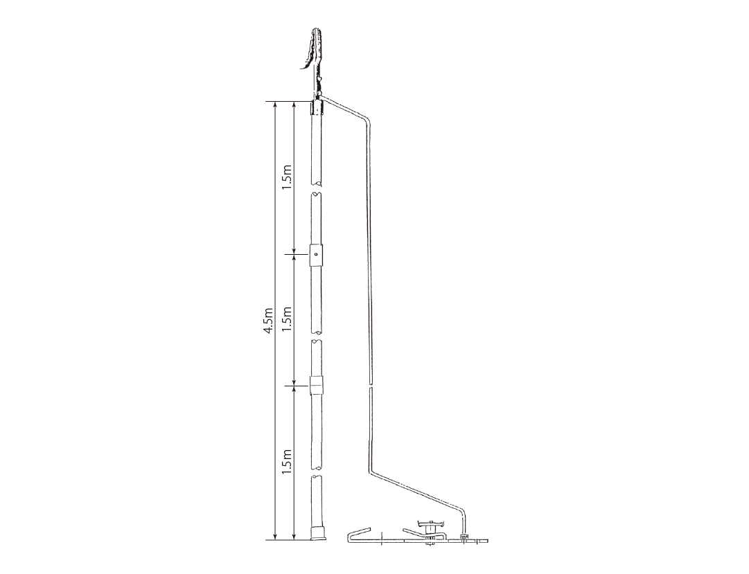
Earthing hooks (standard / type R) 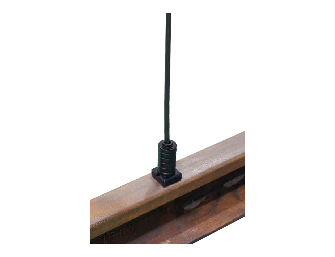
HVC-1.5N3 / HVC-1.5N3S / HVC-1.5N3M 
HVC-750N3 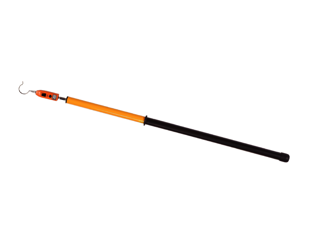
HST-W80JS 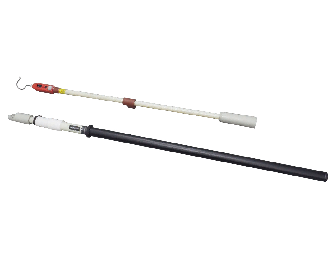
HST-22JX 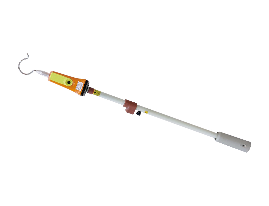
HSR-1.5NJ 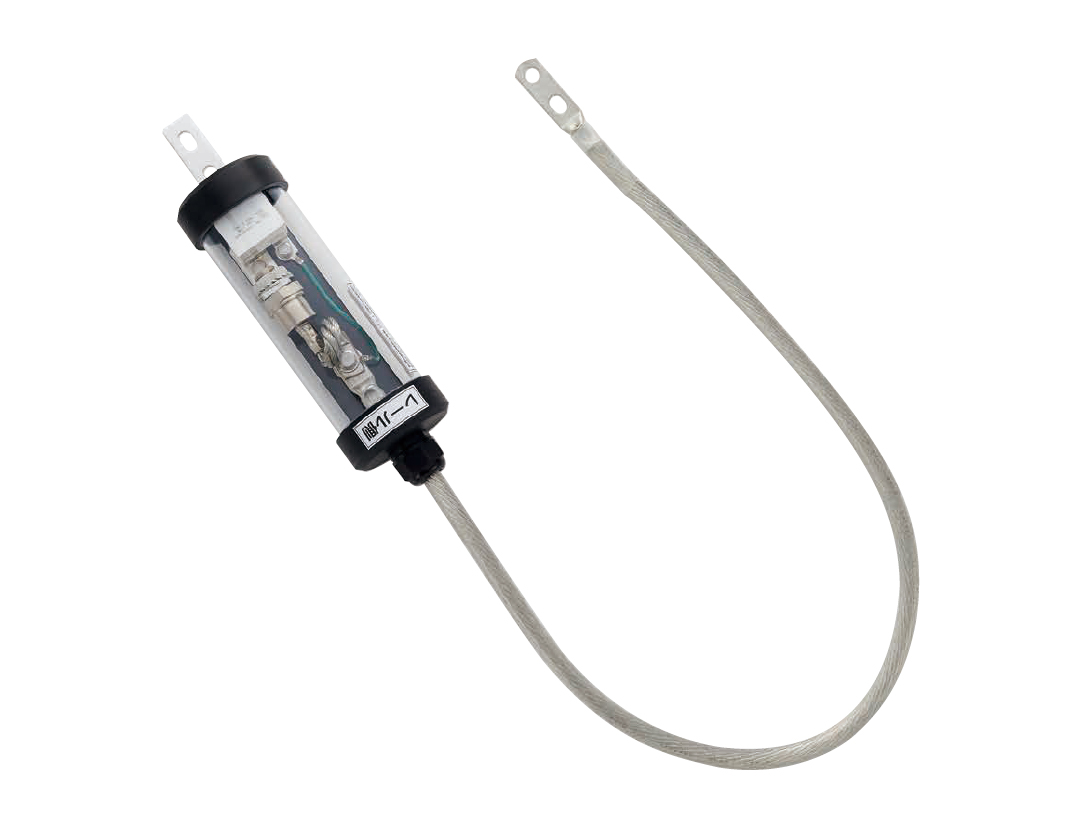
EFS-1 Circuit Guard
Detector testers and measuring instruments
A voltage detector must be checked before every use. Testers that generate a test voltage serve this purpose, together with additional measuring instruments for network maintenance.
| Model | Working voltage | Description |
|---|---|---|
| HLA-1A / HLA-3 / HLA-2G / HLA-N2 | — | Battery-powered portable testers for checking detector function – for LV and HV, for telecommunication versions and for DC detectors. |
| HLL-1 / HLL-6D | — | Wall-mounted testers powered from AC 100 V with outputs for low voltage, high voltage and combined detectors; the HLL-6D covers AC and DC versions. |
| IPR-2 / IPR-2B | — | Measurement of the combined earthing resistance of cable networks in 50 and 60 Hz variants, with an extended range and half the measuring time of the previous generation. |
| LT-2 | — | Measurement of the leakage current of contact lines with its own test voltage source, range DC 0–199.99 mA. |
| HEV-750D | DC 12–750 V | Voltage checking in electric and hybrid vehicles with discrimination between the control and traction circuits and support for discharging residual charge. |
| Model | Working voltage |
|---|---|
| HLA-1A / HLA-3 / HLA-2G / HLA-N2 | — |
| HLL-1 / HLL-6D | AC 100 V |
| IPR-2 / IPR-2B | 50 / 60 Hz |
| LT-2 | DC 0–199.99 mA |
| HEV-750D | DC 12–750 V |
Instrument photos
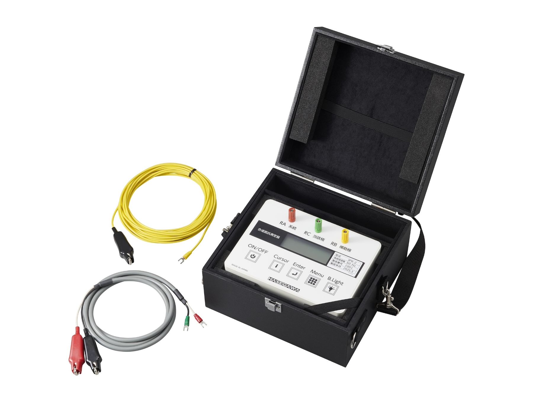
IPR-2 / IPR-2B 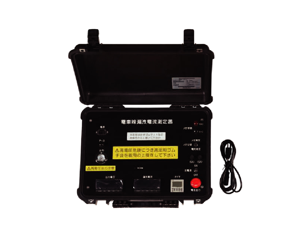
LT-2 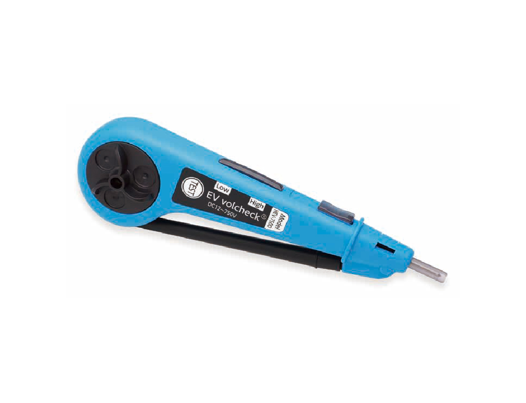
HEV-750D
This overview follows the HASEGAWA ELECTRIC product range. We will confirm the specific models, ranges and accessories according to your application, voltage level and applicable operating rules – ask us for a quotation.